2017-2024 Audi Q7/SQ7 Corroded Splice Points Warning TSB
Audi Technical Service Bulletin 2067722/1 addresses various electrical issues, warning messages, and DTCs like U150600, U028400, and U020800 in 2017-2024 Audi Q7 and SQ7 models. The root cause is often corroded splice points in the driver's sill area.
 Ahmet Topcu2021 Audi Q7
Também se aplica a
- Audi Q7
- 2022–2024
- Audi SQ7
- 2021–2024
Symptoms of Corroded Splice Points
Owners of 2017-2024 Audi Q7 and SQ7 vehicles may experience a range of electrical issues due to corroded splice points in the driver's sill area. These symptoms can be varied and may include:
- Various functional problems, such as issues with the ambient lighting or the MMI (Multi Media Interface).
- Instrument cluster messages and failure of displays.
- Operational issues, including the engine not starting.
- An inoperative driver seat.
- An illuminated check engine lamp.
- Limited function of the ambient lighting.
These issues are often accompanied by specific diagnostic trouble codes (DTCs) stored in multiple control units.
Fault Codes / DTCs
When diagnosing issues related to corroded splice points, technicians may find several DTCs. The following table lists common fault codes and their associated symptoms:
| Splice | Symptom | DTC |
|---|---|---|
| B304 | Driver seat inoperative | No DTC |
| U020800: Lost Communication with Seat Control Module A | ||
| B468 | Secondary air | P041800: Sec. Air Injection System Relay A Circuit |
| P225700: Secondary Air Injection System Control "A" Circuit low | ||
| Motor mount | P157200: Left Electro-Hydraulic Engine Mount Solen.val. Short circuit to ground | |
| P157300: Left Electro-Hydraulic Engine Mount Solen.val. Open circuit | ||
| Radiator shutter | P157600: Right Electro-Hydraulic Engine Mount Solen.val. Short circuit to ground | |
| P157700: Right Electro-Hydraulic Engine Mount Solen.val. Open circuit | ||
| U028400: Lost Communication With Active Grille Air Shutter Module "A" | ||
| B698 | AC system failure | U150600: Local data bus no communication |
| U150C00: Local data bus 11 no communication | ||
| B711 | Ambient lighting inoperative | U150600: Local data bus 5 no communication |
Diagnosis and Trigger Conditions
The underlying cause for these varied electrical problems, including the Audi Q7 corroded splice points, is often the ingress of road salt concentrations into the vehicle. In climates where road salts are used to melt snow, these heavy salt concentrations can enter the vehicle between the driver-side sill and the carpet. When this mixture reaches the body harness, it can cause the splice points at the driver's sill location to become oxidized and corroded.
Diagnosis involves a thorough inspection of the splice points in the driver's sill area. Technicians will look for signs of oxidation and corrosion. The presence of the DTCs listed above, combined with the reported symptoms, helps pinpoint the issue to these specific splice points.
Repair Procedure Summary
Audi Technical Service Bulletin 2067722/1 outlines a detailed repair procedure to address the corroded splice points and restore proper electrical function. The repair involves inspecting and servicing the splice points and, in some cases, installing a new terminal 30 power cable. There are two primary versions for connecting the repair cable:
General Steps for Splice Point Repair
- De-energize the Vehicle: The vehicle's electrical system must be de-energized before starting any repair work.
- Access Splice Points: Carefully open the harness tape of the main vehicle harness located between the A-Pillar and B-Pillar on the driver's side (as shown in Figure 2, which depicts the driver side door sill area with an open harness to expose splice points). A seam ripper is recommended to avoid damaging wires.
- Inspect Splice Points: Visually inspect all splice points in the driver's sill area for damage or corrosion.
- Repair Splice Points: All splice points in this area must be serviced using VAS 1978 B to ensure they are watertight. For non-oxidized splice points, seal them using shrinking end caps. For oxidized splice points, service them with VAS 1978 B, ensuring watertight sealing.
Terminal 30 Cable Installation (Two Versions)
The TSB provides two methods for connecting the repair cable, depending on space availability and technician preference:
Version 1: Cut and Splice Method
This version involves cutting the wire ends from the repair cable at the driver fuse block side and splicing them into the vehicle's existing wiring.
- Connect the repair cable using VAS 1978 B and VAS 631 003.
- Crimp connectors can be used to connect the repair wire, avoiding direct pinning into the fuse holder.
- Important: If using this version, stop wrapping the repair cable at the point where it will be spliced into the vehicle harness. After splicing, continue wrapping both tapes to the fuse block, ensuring splice points are staggered.
Version 2: De-pin and Install Method
This version involves de-pinning the fuse blocks on the driver's side and installing the repair cable without cutting.
- Route individual wires of the repair cable into the fuse block at the driver's side. A chart in the TSB guides correct pinning into the corresponding fuse block location.
Cable Routing and Wrapping
After installing the repair cable (using either Version 1 or 2), the following steps are crucial:
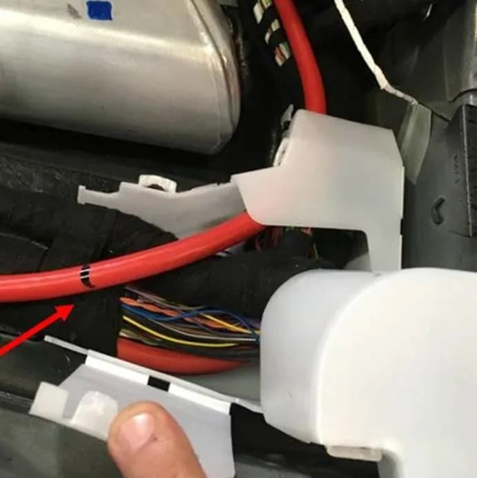
- Test Fit and Mark: Test fit the repair cable in the vehicle. Disconnect the existing cable at E1A and bolt the new repair cable to the power supply terminal at the battery, ensuring flat contact (Figure 3 illustrates the power supply location at the battery). Mark the location on the repair cable just after the cable duct on the rear passenger side (Figure 5 shows the marked location). Figure 4 provides a general view of the terminal 30 cable repair routing.
- Initial Wrapping: Remove the repair cable from the vehicle and wrap it with blue textile tape (N 107 292 04) from power distributor E1A at the battery to the marked location (Figure 6 shows this blue cable wrapping).
- Second Wrapping: Wrap the same section of the repair cable again with gray textile tape (N 107 516 03) (Figure 7 illustrates the gray cable wrapping). It is critical that the wrappings overlap by 50% for crash requirements.
- Permanent Reinstallation: Re-install and route the cable along the exterior of the main harness on the inside facing portion (Figures 8 and 9 show routing paths on the passenger and driver sides, respectively). Secure it with cable ties and textile tape (N 107 290 02) as needed to prevent chafing.
- Main Harness Wrapping: Wrap the entire main wiring harness (including the repair cable) between the A and B pillars on both the driver and passenger sides. First, wrap with blue textile tape (N 107 292 04) (Figure 10 shows the main wiring harness wrapped in blue tape), then rewrap with gray textile tape (N 107 516 03) (Figure 11 shows the gray tape covering the wrapped harness).
Important Warnings
When performing this repair, technicians must adhere to specific routing instructions to ensure the longevity and safety of the electrical system:
- Do not route the cable between the harness and the exterior body.
- Do not route the cable inside (within) the main harness.
- It is not necessary to completely wrap any portion of the repair cable with textile tape N 107 290 02; use it only to secure the cable and prevent chafing.
Required Tools or Parts
The following parts and tools are required to perform the repair described in TSB 2067722/1. Note that these part numbers may differ from those listed in ETKA, and only the ones specified in this TSB should be used.
Part Numbers
| Part Number | Part Description | Quantity |
|---|---|---|
| 021 972 913 C | Shrinkable hose, waterproof D=5.7mm | As required |
| 021 972 913 D | Shrinkable hose, waterproof D=7.4mm | As required |
| 4M1 974 177 | Repair cable (Terminal 30 cable) Q7 only | 1 |
| N 107 292 04 | Blue textile tape | 2 |
| N 107 516 03 | Grey textile tape | 3 |
| N 107 290 02 | Adhesive tape | 1 |
| 000 979 940 | Crimp connector | As required |
| 000 979 941 | Crimp connector | As required |
| 000 979 942 | Crimp connector | As required |
| 000 979 943 | Crimp connector | As required |
| 000 979 944 + | Crimp connector 10mm² + shrinkable hose | As required |
| 000 979 992 A | ||
| N 106 972 01 | Cable tie | Shop supply |
Tools
| Tool Number | Tool Description |
|---|---|
| Locally sourced | Seam ripper |
| VAS 1978 B | Wire harness repair set |
| VAS 631 003 | Crimp connector kit |
| VAS 6160 / VAS 6150 | VAS tester with the current version of ODIS (Windows 10) |
Warranty Information
This repair, identified by Audi Technical Service Bulletin 2067722/1, falls under specific warranty claim procedures. The Service Number for this issue is 9709, and the Damage Code is 0033.
Labor operations for this repair vary slightly by model year:
- Up to model year 2019: Removing and installing floor covering (front and rear) is coded as 7041 1999 (570 TU).
- From model year 2020 onwards: Removing and installing floor covering (front and rear) is coded as 7041 1999 (540 TU).
- All Model years: Servicing all splice points in the driver sill area is coded as 9709 4199 (240 TU).
Diagnostic time is GFF (0150 0000). Road tests prior to and after the service procedure are also accounted for (0 TU and 10 TU respectively).
Warranty claims must be submitted in accordance with the Audi Warranty Policies and Procedures Manual and are subject to review or audit by Audi Warranty. If the vehicle is outside of any warranty, this Technical Service Bulletin is informational only, meaning the repair cost may not be covered.
Source: NHTSA ID: 10218947, TSB 2067722/1
Galeria
10 imagens
Frequently Asked Questions
- What are the common symptoms of corroded splice points in an Audi Q7 or SQ7?
- Owners may experience various electrical issues, including instrument cluster warnings, inoperative displays or ambient lighting, problems with the MMI, an inoperative driver seat, or the engine failing to start. An illuminated check engine lamp is also a common symptom.
- Which DTCs are associated with the Audi Q7 corroded splice points issue?
- Diagnostic Trouble Codes (DTCs) such as U150600, U028400, U020800, P041800, P225700, P157200, P157300, P157600, P157700, and U150C00 are commonly found when corroded splice points are the root cause of electrical problems in affected Audi Q7 and SQ7 models.
- How is the corroded splice point issue repaired in Audi Q7/SQ7 models?
- The repair, detailed in Audi TSB 2067722/1, involves inspecting and repairing oxidized splice points in the driver's sill area, often requiring the installation of a new terminal 30 power cable. The procedure includes specific steps for cable routing, wrapping with textile tape, and ensuring watertight connections.
- Is this repair covered under warranty?
- This repair may be covered under warranty, with specific labor operations and codes (Service Number 9709, Damage Code 0033) outlined in TSB 2067722/1. However, coverage depends on the vehicle's warranty status and adherence to Audi Warranty Policies and Procedures Manual. If the vehicle is outside of warranty, the bulletin serves as informational guidance.
- What specific parts and tools are needed for this repair?
- Key parts include various shrinkable hoses, a specific repair cable (4M1 974 177 for Q7), blue and grey textile tapes (N 107 292 04, N 107 516 03), adhesive tape (N 107 290 02), and several crimp connectors. Required tools include a seam ripper, a wire harness repair set (VAS 1978 B), a crimp connector kit (VAS 631 003), and a VAS tester with ODIS software.
Outras revisões deste TSB
- 2023 Audi A6 Check Engine Light & Harness Chafing TSBP157200, P157600
- 2021-2023 Audi Q8 Corroded Splice Points TSBU150600, U028400, U020800
- 2019-2023 Audi Q8/SQ8/RS Q8 Corroded Splice Points TSB 2067785/1U150600, U028400, U020800
Related Articles
2021-2026 Audi Q7/SQ7 Second Row Seat Noise TSB
Audi Technical Service Bulletin 2060719/4 details a common complaint of creaking and rattling noises from the second row seats in 2021-2026 Audi Q7 and SQ7 models. The issue stems from friction between the seat's lock handle and the locking mechanism.
2021-2024 Audi Q7 Parts Return Communication
This manufacturer communication, identified by NHTSA ID 11002296, informs Audi dealers about a special notice concerning the return of specific body structure parts for 2021-2024 Audi Q7 vehicles.
2021-2024 Audi Q5/Q7/SQ5/SQ7 Taillight Switching Issue B146C29
Audi has released TSB 2070964/2 addressing a functional issue with taillight switching in 2021-2024 Q5, Q7, SQ5, and SQ7 models. Owners may experience taillights not switching correctly or staying on, often accompanied by DTC B146C29. The fix involves checking for and removing debris.
2021-2024 Audi Power Rear Lid Malfunction
If your 2021-2024 Audi's power rear lid is not opening or closing, you may be experiencing a known issue addressed by Technical Service Bulletin (TSB) 2072288/3. This TSB covers Diagnostic Trouble Codes (DTCs) B121102 and B120A02, indicating a software problem.
2021-2023 Audi Q7/SQ7 Radiator Fan & Wiper Malfunction
Audi Technical Service Bulletin 2073305/1 details issues with constant radiator fan operation, non-functional windshield wipers, and alarm system faults in 2021-2023 Audi Q7 and SQ7 vehicles. These problems are often linked to damaged wiring in the plenum chamber and are accompanied by specific…
Leave a comment
Comments are moderated and may take a moment to appear. Only your first name and the initial of your last name are shown publicly.
Comments
Be the first to comment.