2017-2024 Audi Gearbox Warning and DTCs TSB
Audi has released Technical Service Bulletin 35 23 44 2070217/1 to address issues where a gearbox warning appears, the vehicle shudders, or enters limp mode, often accompanied by various DTCs like P173500. The repair involves replacing components within the transmission control unit.
 Sarah Mitchell2022 Audi S3
S'applique également à
- Audi A3
- 2022–2024
- Audi RS 3
- 2022–2024
- Audi S3
- 2023–2024
- Audi TT
- 2021–2023
- Audi TT RS
- 2021–2022
- Audi TTS
- 2021–2023
Owners of various 2017-2024 Audi models, including the Audi S3, may encounter a persistent Audi S3 gearbox warning or other transmission-related issues. This Technical Service Bulletin (TSB) 35 23 44 2070217/1, issued on September 15, 2023, addresses these concerns, which stem from a hardware problem within the transmission control unit (TCM).
This TSB outlines a detailed diagnostic and repair process for technicians to follow when customers report specific symptoms and corresponding fault codes are stored in the vehicle's memory. The repair primarily involves replacing internal components of the mechatronic unit, ensuring the transmission operates correctly and safely.
Symptoms
Owners may notice one or more of the following conditions indicating a problem with their vehicle's gearbox:
- The vehicle shudders while driving.
- The gearbox warning lamp is illuminated on the dashboard.
- The instrument cluster displays the message "Gearbox Malfunction".
- The gearbox operates in Limp Home Mode, allowing only specific gears (1-3-5-7 or 2-4-6) to be used.
Fault Codes / DTCs
When these symptoms occur, the Transmission Control Module (TCM), identified as -J217- (address word 0002), may store one or more of the following Diagnostic Trouble Codes (DTCs):
| DTC Entry | Symptom Code | Description | Gearbox Type |
|---|---|---|---|
| P173500 | 10666 | Clutch position sensor 1, electrical malfunction | 0GC/0DL |
| P173600 | 10668 | Clutch position sensor 2, electrical malfunction | 0GC/0DL |
| P175D00 | 10693 | Clutch 1 opens unintentionally | 0GC/0DL |
| P176E00 | 10694 | Clutch 2 opens unintentionally | 0GC/0DL |
| P175E00 | 10747 | Clutch 1 closes unintentionally | 0GC/0DL |
| P176F00 | 10748 | Clutch 2 closes unintentionally | 0GC/0DL |
| P060700 | 10658 | Control module implausible | 0GC/0DL |
| P060700 | 10660 | Control module implausible | 0GC/0DL |
| P060700 | 10662 | Control module implausible | 0GC/0DL |
| P060700 | 10664 | Control module implausible | 0GC/0DL |
| P176A00 | 10912 | Gear selector 1 cannot be regulated | 0GC/0DL |
| P176B00 | 10913 | Gear selector 2 cannot be regulated | 0GC/0DL |
| P176C00 | 10914 | Gear selector 3 cannot be regulated | 0GC/0DL |
| P176D00 | 10915 | Gear selector 4 cannot be regulated | 0GC/0DL |
| P176A00 | 10725 | Gear selector 1 cannot be regulated | 0GC/0DL |
| P176B00 | 10726 | Gear selector 2 cannot be regulated | 0GC/0DL |
| P176C00 | 10727 | Gear selector 3 cannot be regulated | 0GC/0DL |
| P176D00 | 10728 | Gear selector 4 cannot be regulated | 0GC/0DL |
| P071500 | 10753 | Transmission Input Speed Sensor 1, electrical fault in circuit | 0GC/0DL |
| P276500 | 10754 | Transmission Input Speed Sensor 2, electrical fault in circuit | 0GC/0DL |
| P174A00 | 10739 | Valve 3 in partial transmission 1 electrical malfunction | 0DL |
| P174E00 | 10740 | Valve 3 in partial transmission 2 electrical malfunction | 0DL |
| P173E00 | 10741 | Valve 1 in partial transmission 1 electrical malfunction | 0DL |
| P174C00 | 10742 | Valve 1 in partial transmission 2 electrical malfunction | 0DL |
| P173F00 | 10743 | Valve 2 in partial transmission 1 electrical malfunction | 0DL |
| P174D00 | 10744 | Valve 2 in partial transmission 2 electrical malfunction | 0DL |
Diagnosis and Trigger Conditions
Diagnosis for the Audi S3 gearbox warning begins with checking the Transmission Control Unit's (TCM) software part number and version. The TCM is identified as -J217- (address word 0002) and its system name is "02 - Transmission Electronics (7-sp)". Technicians must verify the installed Software part number and Software version number against a specific table in the TSB. For example, a vehicle might have Hardware part number 0GC927711H, Part number 0GC300044H, Hardware version H06, and Software version 2402 (as shown in Figure 1 of the TSB). If the installed software part number and version are not listed in the provided table, this TSB does not apply, and diagnosis should continue outside of this bulletin.
The Offboard Diagnostic Information System (ODIS) must have a baseline version (diagnosis data – didb_GFS-a) of 2023.03.01 / 2.30.5 or higher installed for accurate diagnosis (Figure 2). The TSB specifies GFF DIDB version 2023.05.01, GFF technical version 2.31.1, and Base DIDB version 2023.5.2.AutoGenerated. During the diagnostic session, it is crucial that 89 values are read out and transmitted in the global variables under address DA0002. This can be verified by saving the diagnostic protocol (Figure 3) and checking the number of DA0002 entries (Figure 7). If fewer than 89 values are present, this TSB repair will not work and does not apply to the vehicle; repairs must be conducted according to ODIS test plans and the repair manual.
Guided Fault Finding is then performed for the relevant event memory entry. Technicians must answer 'YES' when prompted about locating a relevant Technical Service Bulletin or Technical Product Information (TPI) and enter TPI number 2058356. The 4-letter index of the Mechatronic unit (e.g., 0GCE, as shown in Figure 8) must be noted and compared to the parts list tables in the TSB to confirm applicability. If the index is not found in the parts lists, the TSB does not apply.
Important Warnings for Owners and Technicians
- TSB Applicability: "If the installed Software part number and Software version number is not included in the table below, then this TSB does not apply. Continue the diagnosis and repair outside of this TSB."
- Diagnostic Data: "It is only possible to receive the correct control unit if the diagnostic log was sent with the relevant event memory entry, the completed test plan, and the 89 values shown in the Global Variables." Also, "If there are less than 89 values this TSB repair will not work, and it does not apply to the vehicle. Repairs should be made outside this TSB according to ODIS test plans and the repair manual."
- Part Ordering: "Parts cannot be ordered until Step 11 of this TSB has been completed and the index of the Mechatronics unit is shown in one of the lists below! It is only possible to deliver the correct control unit if the diagnostic log was sent online with the relevant DTC entry and the completed test plan." Furthermore, "Only order parts for the correct index of the Mechatronics unit! If the installed mechatronics unit does not have index that matches one of the parts tables below this TSB does not apply to the vehicle!" All parts must be ordered using the VIN of the vehicle.
- Immobilizer Readaptation: "The immobilizer must be readapted after replacing the control unit. For this purpose, it is essential that all vehicle keys are present at the time of the repair."
- Mechatronic Unit Handling: "The sensors are on the back of the mechatronic unit and must not be touched/damaged. The mechatronic unit must not be placed down on its sensors" (Figure 9). Technicians must "take care not to damage the valve contacts and the sensors" when handling. "It is essential to ensure that the contacts on the valves are not bent or damaged" during contact plate removal.
- Cleanliness: "You must ensure the highest levels of cleanliness for all work on the mechatronic unit. Even the smallest dirt particles or hairs in the system can lead to restricted functions and ultimately to failure of the mechatronic unit."
Repair Procedure Summary
The repair procedure outlined in TSB 35 23 44 2070217/1 involves replacing specific internal components of the mechatronic unit. After confirming the TSB's applicability through diagnostic checks, the technician will:
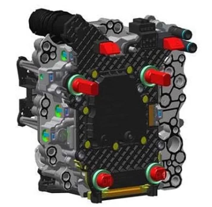
- Remove the Mechatronic Unit: The mechatronic unit is carefully removed from the gearbox according to the repair manual.
- Handle with Care: The unit is placed in an assembly aid to protect the sensors (Figure 10). A special tool, the VAS 6613 ESD Work Surface, is required to prevent electrostatic discharge when working on electrical components. Technicians must touch an earthed object before working and avoid direct contact with sensors or electronic components. The new control unit from its packaging is stored safely, and the mechatronic unit is placed in the assembly aid with sensors facing downwards.
- Detach Contact Plate: The contact plate is detached from the mechatronic unit by loosening and removing its bolts (Figure 11 for 0GC Transmission or Figure 12 for 0DL Transmission). This must be done carefully, starting from the top corners, to ensure the valve contacts are not bent or damaged (Figure 13).
- Position for Control Unit Removal: The mechatronic unit is taken out of the assembly aid, turned over, and placed back in the aid with the control unit facing upwards (Figure 14). The connecting tab between the contact plate and the control unit is moved (Figure 15) until it engages with an audible click.
- Remove Gearbox Control Unit: The four bolts (A, D short and B, C long) for the transmission control unit are unscrewed (Figure 16), and the gearbox control unit is carefully detached upwards from the mechatronic unit.
- Replace Pressure Sensor Seals: The seals for the pressure sensors are replaced, ensuring they are correctly seated (Figure 17).
- Reassemble Control Unit: The control unit is reassembled with new bolts and tightened in two stages according to specific torque values and sequences:
- Stage 1: Bolts A and D (short) are tightened to 6 Nm. Bolts B and C (long) are tightened to 4.5 Nm.
- Stage 2: Bolts A and D (short) are tightened to 8 Nm + 30°. Bolts B and C (long) are tightened to 5 Nm + 25°.
- Fit New Contact Plate: The new contact plate is fitted, ensuring it engages audibly. It is critical that all contacts are inserted into the correct connector and are not bent (Figure 18 shows correct contact, Figure 19 shows bent contact).
- Tighten Contact Plate: The contact plate is tightened with new bolts in a specified two-stage sequence:
- For 0GC Transmission (Figure 20): Stage 1: 2 Nm. Stage 2: 3 Nm + 30°. Tightening sequence: 1 -> 2 -> 3 -> 12 -> 5 -> 4 -> 11 -> 10 -> 9 -> 8 -> 6 -> 7.
- For 0DL Transmission (Figure 21): Stage 1: 2 Nm. Stage 2: 3 Nm + 45°. Tightening sequence: 1 -> 2 -> 3 -> 4 -> 5 -> 6 -> 7 -> 8 -> 9 -> 10 -> 11.
- Final Assembly and Activation: The mechatronics unit is reassembled with a new cover and installed back into the transmission, including refilling the transmission with oil according to the repair manual. The new control unit is activated using the Guided Function "0002 - Replace mechatronic unit (control unit)", followed by performing a basic setting for the gearbox.
Required Tools or Parts
Performing this repair requires specific tools and genuine Audi parts. Technicians must consult ETKA/ELSA for the latest information and part bulletins, and order all parts using the vehicle's VIN.
Special Tools:
- VAS 6613 ESD Work Surface
Key Parts (quantities may vary based on specific mechatronic unit index and transmission type, e.g., 0GCB, 0GCC, 0GCD, 0GCE, 0GCH, 0BH, or 0DL):**
- Control units: 0GC 927 711 G VI1, 0GC 927 711 H VI1 (Qty: 01)
- Contact plates: 0GC 927 709 A, 0BH 927 709 A (Qty: 01)
- Bolts for control unit: N 101 243 04 (short, Qty: 02), N 104 057 05 (long, Qty: 02)
- Bolts for contact plate: N 904 552 02 (Qty: 12)
- O-rings for pressure sensor: WHT 004 007 B (Qty: 02)
- Cover for mechatronic unit: 0GC 325 201 H (Qty: 01)
- Bolts for mechatronic unit: N 105 540 02 (Qty: 09)
- Bolts for cover for mechatronic unit: N 910 327 02 (Qty: 04)
- Retaining clip: 0BH 325 147 (Qty: 01)
- Oil seals: N 043 809 2 (Qty: 01), N 013 813 2 (Qty: 01)
- Gear oil: G 055 529 A2 (Qty: 07), G 052 182 A2 (Qty: 07)
- Fasteners, bolts, nuts, and screws as needed per the repair manual.
Warranty Information
This repair, identified by TSB 35 23 44 2070217/1, is covered under Audi's warranty policy for up to 48 months or 50,000 miles, whichever comes first. For Certified Pre-Owned (CPO) vehicles, coverage falls under G10, and owner verification is required. "If the vehicle is outside any warranty, this Technical Service Bulletin is informational only." The service number for this repair is 3511, with a damage code of 0040. Labor operations include "Remove and install mechatronic unit" (code 3511 19xx) and "Repair mechatronic unit" (code 3511 4199), with an estimated time unit (TU) of 50. Diagnostic time is allocated as GFF 0150 0000, with a maximum of 120 TU. Road tests before and after the service procedure have no allowance and are allocated 0 TU.
All warranty claims must adhere to the Audi Warranty Policies and Procedures Manual and are subject to review or audit by Audi Warranty.
NHTSA ID: 10242931
Galerie
14 images
Frequently Asked Questions
- What does the 'Gearbox Malfunction' message mean in my Audi?
- The 'Gearbox Malfunction' message, often accompanied by vehicle shuddering or the car entering limp mode, indicates a hardware issue within the Transmission Control Unit (TCM). Audi TSB 35 23 44 2070217/1 addresses this by outlining a repair for the mechatronic unit.
- Which Audi models are affected by TSB 35 23 44 2070217/1?
- This TSB applies to various 2017-2024 Audi models, including the A3, S3, RS 3, TT, TT Roadster, and TTS. It's crucial to check the specific software and part numbers of your vehicle's Transmission Control Unit to confirm applicability.
- What are common DTCs associated with an Audi S3 gearbox warning?
- Common Diagnostic Trouble Codes (DTCs) include P173500 (Clutch position sensor 1, electrical malfunction), P173600 (Clutch position sensor 2, electrical malfunction), and various P060700 codes indicating an implausible control module. A full list of potential DTCs is provided in TSB 35 23 44 2070217/1.
- Is the repair for the Audi gearbox warning covered under warranty?
- Yes, the repair is generally covered under Audi's warranty for up to 48 months or 50,000 miles. For Certified Pre-Owned vehicles, G10 coverage applies. If your vehicle is outside of warranty, the TSB serves as informational guidance, and costs may apply.
- Are there any special precautions during this gearbox repair?
- Yes, technicians must use a VAS 6613 ESD Work Surface to prevent electrostatic discharge. Extreme cleanliness is required, and the delicate sensors on the mechatronic unit must not be touched or damaged. Additionally, all vehicle keys must be present for immobilizer readaptation if the control unit is replaced.
Autres révisions de ce TSB
- 2021-2024 Audi Gearbox Malfunction DTCs P173500, P173600P173500, P173600
- 2021-2024 Audi A3/TT Gearbox Malfunction TSB 2070217/2P173500, P060700, P176A00
- 2021-2022 Audi e-tron ABS Warning Light and DTC P060700P060700
Related Articles
2022-2023 Audi MIB3 MMI Software Update for Emergency Call Fault
Audi has issued Technical Service Bulletin (TSB) 2079134/4 for 2022-2023 A3, S3, RS 3, e-tron GT, and RS e-tron GT vehicles equipped with MIB3 infotainment systems. This TSB addresses various MMI function problems and the 'Emergency call fault' message by providing a critical software update.
2021-2024 Audi A3/S3/TT Whining Noises TSB 2074764/2
Audi Technical Service Bulletin 2074764/2 describes whining noises from the rear end of 2021-2024 Audi A3, S3, and TT models during acceleration or deceleration. This TSB clarifies that these noises are comfort-related and replacing parts will not resolve the issue.
2022-2025 Audi MIB3 Volume Control Not Working TSB U11B900
Audi has released Technical Service Bulletin 2072873/6 to address issues with the MIB3 infotainment system's volume control and skip buttons not working in 2022-2025 A3, S3, RS 3, e-tron GT, and RS e-tron GT models. The problem is linked to DTC U11B900, indicating a software issue requiring an…
2022-2023 Audi MIB3 Conbox Software Update
Audi has released a software update for the conbox component within the MIB3 infotainment system. This update, detailed in manufacturer communication NHTSA ID 11027377, applies to various 2022-2023 Audi A3, S3, RS 3, e-tron GT, and RS e-tron GT models.
2022-2024 Audi A3/S3/RS3 Exterior Lighting Warning TSB 2074786/3
Audi Technical Service Bulletin 2074786/3 details a 'Warning lamp for exterior lighting' issue in 2022-2024 A3, S3, RS3, and Q4 e-tron vehicles. This TSB addresses DTCs U112100, U110B00, and B126A29, often resolved by light switch replacement.
Leave a comment
Comments are moderated and may take a moment to appear. Only your first name and the initial of your last name are shown publicly.
Comments
Be the first to comment.