2021-2023 Audi A4, A5, S4, RS 5 Creaking Noise TSB
Audi Technical Service Bulletin (TSB) 2062633/2 addresses creaking noises in 2021-2023 Audi A4, A4 allroad, A5, S4, and RS 5 models during braking or steering maneuvers. The TSB details a repair to resolve contact between the longitudinal member and its reinforcement plate.
 Marcus Weber2021 Audi A5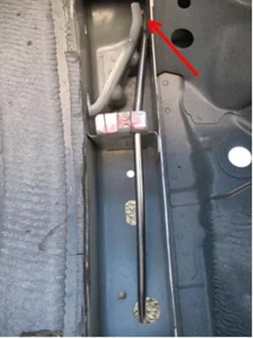
Gilt auch für
- Audi A4
- 2021–2023
- Audi A4 allroad
- 2021–2022
- Audi A5
- 2022–2023
- Audi RS 5
- 2021–2023
- Audi S4
- 2021–2023
Owners of 2021-2023 Audi A4, A4 allroad, A5, S4, and RS 5 models may experience a creaking noise when the vehicle body twists, particularly during braking or steering maneuvers. This issue, which can manifest as an Audi A5 creaking noise, is addressed by Audi Technical Service Bulletin (TSB) 50 23 12 2062633/2. This bulletin provides detailed instructions for diagnosing and repairing the source of these noises, ensuring a quieter and more comfortable driving experience.
This Technical Service Bulletin (TSB) 50 23 12 2062633/2, issued on March 17, 2023, supersedes an earlier bulletin, Group 50 number 21-06, dated March 19, 2021. The revision history indicates that the latest version includes updates to the header (adding Model Year 2023), warranty information (SRT change), and required parts and tools (specifically, a change in cavity wax material).
Symptoms
Owners may report hearing a "creaking type noise is heard in the floor area." This Audi A5 creaking noise is typically noticeable during specific driving conditions. The noise can be generated during strong braking or steering maneuvers, especially when the vehicle body is under stress and twists. Workshop findings confirm that the noise originates from the floor area, specifically radiating from the footwell to the area under the seat.
Technical Background
The root cause of the creaking noise is identified as contact between the longitudinal member reinforcement plate 'P' and the threaded console 'T' at point 'U'. This contact occurs during cornering or hard braking maneuvers, as illustrated in Figure 1 of the TSB, which shows a cutaway view of the longitudinal member. Audi has implemented improvements in the construction of the longitudinal member assembly in newer production vehicles, but existing vehicles may still exhibit this condition.
Diagnosis Procedure
To accurately diagnose the creaking noise and confirm it falls within the scope of TSB 50 23 12 2062633/2, technicians follow a specific procedure:
- Noise Duplication: Conduct a test drive, ideally with the customer present, to replicate the noise and clearly identify the conditions under which it occurs. Determine from which side of the vehicle the noise originates.
- Initial Subframe Adjustment: Loosen the frontmost bolt on the subframe mounting, as indicated in Figure 2. The bolt only needs to be loosened several turns but must not be removed at this stage.
- Audible 'Cracking' during Loosening: In many cases, an audible 'cracking' noise may be heard during the process of loosening and tightening the subframe bolt, as depicted in Figure 3.
- Post-Adjustment Test Drive: Test drive the vehicle again. If the noise characteristics change or the noise is eliminated, the repair outlined in this TSB is likely to be effective. If no change occurs, further diagnosis outside the scope of this TSB is required.
- Cold Condition Duplication: If the noise is difficult to reproduce when the vehicle is cold, warm up the longitudinal member/body in the area of the rear transverse link. Use a hot air blower set for an outlet temperature of approximately 550°C (1022°F), as shown in Figure 4. This process warms the surface to approximately 65°C (149°F), as seen in Figure 5.
- Cooling and Re-test: Allow the surface temperature to cool to approximately 30°C (86°F), as shown in Figure 6, then test drive the vehicle again. Merely lowering the vehicle from the hoist can sometimes immediately elicit the noise symptom after this warming process.
Repair Procedure Summary
Once the creaking noise is confirmed to be related to the longitudinal member, the repair involves creating a necessary gap and applying corrosion protection. The procedure includes:
- Accessing the Area: Remove the front middle underbody trim 'B', front underbody trim 'C', and the underbody trim 'D', as illustrated in Figure 7. To gain access to the affected area inside the longitudinal member, unscrew the four sheet nut fasteners 'F' for the heat shield. Bend the heat shield slightly away from the longitudinal member and remove grommet 'E', as shown in Figure 8.
- Grommet Removal: Remove grommet 'H' from the longitudinal member, as depicted in Figure 9.
- Bolt Replacement: The bolt 'G', which was loosened during the diagnosis process, must be replaced. Use the installation and tightening procedure specified in ElsaPro for this replacement.
- Impact Protector Removal: Remove the impact protector 'K' by prying out clip 'I' from the impact protector and then removing it from the longitudinal member, as shown in Figures 10 and 11.
- Internal Access: Shine a flashlight through opening 'K' (from where the impact protector was removed) to view the upper round hole 'M' in the longitudinal member reinforcement plate 'N'. This is viewed through hole 'L' (the hole from grommet 'E'), as illustrated in Figures 12 and 13.
- Tool Fabrication: An improvised tool is necessary for this modification. Obtain a steel rod 10mm in diameter and 50cm long. Grind the tip of one end into a chisel shape, with the grind length being 15mm +/- 3mm on each side, as shown in Figure 14.
- Tool Bending: Mount one end of the rod into a vice, 11cm deep, with the chisel shape parallel to the ground (Figure 15). Create a bend 11cm from the chisel end until a distance of 43mm +/- 3mm is achieved between the axis of the longer end of the rod and the axis of the shorter end at its tip, as shown in Figure 17. Measure and verify this distance, as depicted in Figure 18.
- Tool Insertion: Insert the chisel end of the fabricated steel rod 'A' into the body opening 'L' in the longitudinal member (Figure 19). Then, feed the steel rod 'A' through hole 'M' (the upper hole) in the reinforcement plate, as shown in Figure 20.
- Engaging the Reinforcement Plate: The chisel end of the steel rod must be fed far enough to engage the front reinforcement plate 'P' at point 'O' such that it is lodged into the gap between reinforcement plate 'P' and the wall of the longitudinal member 'R', as shown in Figure 21. Figure 22 provides a cutaway view illustrating the correct steel rod positioning, while Figure 23 shows the chisel end properly engaged. Figure 24 illustrates an incorrect engagement.
- Creating the Gap: Using a marker, mark the point on the steel rod where it makes contact with the longitudinal member. Then, make another mark 10mm to 15mm rearward of that contact point, as shown in Figure 25. Using a hammer, drive the steel rod forward a distance of 10mm (Figure 26). After this, pull the bending tool out of the longitudinal member. This action creates a gap of approximately 3mm between the reinforcement plate 'P' and the longitudinal member 'R' (Figure 27), which effectively separates the contact point and eliminates the noise generation.
- Corrosion Protection: All points that were contacted and/or struck during the procedure are likely to have had their corrosion protective layer compromised. Thoroughly coat all these areas with cavity wax, as shown in Figure 28. Cavity wax can be applied through various openings, including hole 'S', as indicated in Figure 29.
- Reassembly and Final Test: Reassemble the vehicle according to the repair manual. Perform a final test drive to confirm the complete elimination of the noise by duplicating the driving conditions specified by the customer. Ensure the noise has been eliminated to the customer's satisfaction by driving with the customer when they take possession of the vehicle after repair.
Important Warnings
- As specified in the repair manual, it is necessary to replace all loosened subframe bolts at the conclusion of the entire repair. These bolts are not to be reused after being loosened during the diagnostic or repair process.
- If the initial diagnostic step (loosening the subframe bolt and re-testing) does not change or eliminate the noise, the repair described in this TSB will not be effective. In such cases, diagnosis must continue outside the scope of this specific repair procedure.
Required Tools and Parts
Technicians will need the following parts and materials for this repair:
- Fasteners: Various fasteners, bolts, nuts, and screws as needed per the repair manual (refer to ETKA/ELSA).
- Anti-Corrosion Wax: Part number D 321 M15 M1 (Quantity: 01).
- Alternative Cavity Wax: 3M™ Cavity Wax Plus 08852 (Shop Supply).
- Bolt: Hex head bolt (Quantity: 02, refer to ETKA).
- Improvised Tool: A steel rod, 10mm in diameter and 50cm long, which must be ground to a chisel shape with a 15mm +/- 3mm grind length and bent to specific dimensions (43mm +/- 3mm offset) as detailed in the repair procedure.
Warranty Information
This TSB applies to vehicles under warranty, specifically up to 48 months or 50,000 miles. For vehicles outside this warranty period, the Technical Service Bulletin is informational only. All warranty claims must be submitted in accordance with the Audi Warranty Policies and Procedures Manual, subject to review and audit by Audi Warranty. The service number for this procedure is 5079, with a damage code of 0010.
Labor operations for this TSB include:
- Check longitudinal member: Labor operation 5079 0199, 40 Time Units (TU).
- Modify longitudinal member: Labor operation 5079 4199, 100 TU.
- Modify both longitudinal members: Labor operation 5079 4299, 130 TU.
Diagnostic time is also covered:
- GFF (Guided Fault Finding): No allowance, 0 TU.
- 3 Road tests prior to the service procedure: Labor operation 0121 0199, 30 TU.
- Road test after the service procedure: Labor operation 0121 0004, 10 TU.
All claims should include the comment "As per TSB 2062633/2."
NHTSA ID: 10233300
Galerie
28 Bilder
Frequently Asked Questions
- What causes the creaking noise in my Audi A4, A5, S4, or RS 5 during braking or steering?
- According to Audi TSB 50 23 12 2062633/2, the creaking noise is caused by contact between the longitudinal member reinforcement plate and the threaded console, particularly when the vehicle body twists during maneuvers like braking or steering.
- How does Audi fix the creaking noise issue described in TSB 2062633/2?
- The repair involves creating a precise 3mm gap between the longitudinal member reinforcement plate and the longitudinal member using a specially fabricated tool. After creating the gap, all affected areas are coated with corrosion protection cavity wax, and the vehicle is reassembled.
- Is the repair for the Audi A5 creaking noise covered under warranty?
- Yes, this repair is typically covered under Audi's warranty for vehicles up to 48 months or 50,000 miles. For vehicles outside this period, the TSB serves as informational guidance, and costs may vary. The specific service number is 5079 and damage code is 0010.
- What should I do if my Audi is making a creaking noise from the floor area?
- If you hear a creaking noise from the floor area, especially during braking or steering, you should contact an authorized Audi service center. Reference TSB 50 23 12 2062633/2 to ensure technicians are aware of the specific diagnostic and repair procedure for this known issue.
Related Articles
2021-2026 Audi Cracking/Creaking Noises During Load Changes TSB
Audi has issued Technical Service Bulletin 2062633/6 to address cracking and creaking noises that may occur in 2021-2026 Audi models during vehicle load changes or severe body torsion. This TSB outlines a repair for a loose bonded joint in the subframe connection.
2020-2021 Audi MIB3 Favorites, Destinations Deleted TSB
This Technical Service Bulletin (TSB) 2079619/1 addresses a software issue in 2020-2021 Audi A4, A5, S4, S5, and RS5 models where the MIB3 system sporadically deletes last destinations, favorites, and home addresses. A software update is required to resolve this problem.
2021-2025 Audi Cracking/Creaking Noises TSB 2062633/4
Audi has issued TSB 2062633/4 to address cracking/creaking noises in 2021-2025 models. This noise, often heard during load changes or body torsion, originates from a loose bonded joint in the subframe. The TSB outlines a repair procedure involving a modified longitudinal member and cavity sealing.
2021-2025 Audi A4/A5 Engine Coolant Temperature Sensor TSB
This Technical Service Bulletin (2078939/1) from Audi addresses a specific diagnostic trouble code, P218500, related to the Engine Coolant Temperature Sensor 2 Circuit High. Owners may notice the exhaust emissions warning lamp (MIL) illuminating on the instrument cluster.
2021-2026 Audi Camera Part Return Notice SM 15-2025
Audi's Special Notice SM 15-2025 instructs dealers to return specific camera part numbers that are not "generation 03S" by March 18, 2025, to ensure customers receive correct parts.
Leave a comment
Comments are moderated and may take a moment to appear. Only your first name and the initial of your last name are shown publicly.
Comments
Be the first to comment.