2019-2024 Audi e-tron J1050 Diagnostic Address Issue TSB 2063427/12
This Technical Service Bulletin (TSB) 2063427/12 from Audi addresses a specific issue affecting the high-voltage battery charger control module (J1050) in 2019-2024 Audi e-tron and e-tron Sportback vehicles. Owners may find that after replacing the J1050 module, it reports under an incorrect…
 Ahmet Topcu2023 Audi e-tron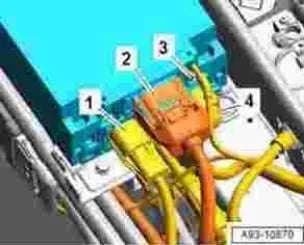
Also applies to
- Audi e-tron
- 2021–2022
- Audi e-tron Sportback
- 2021–2022
Symptoms
Owners of certain Audi e-tron and e-tron Sportback models from 2019 to 2024 may encounter issues related to the high-voltage battery charger control module, identified as J1050. The primary concern arises when this module, which normally operates under diagnostic address 00C6, needs replacement due to a fault. Following the replacement, the new J1050 unit might fail to report under its correct diagnostic address 00C6 in the scan tool. Instead, it may incorrectly appear under diagnostic address 8113.
Another critical symptom associated with this problem is that the vehicle's "high-voltage system cannot be restarted." This can lead to a non-operational vehicle and may be accompanied by specific event memories logged in diagnostic address 0019. These symptoms indicate a communication or configuration error within the vehicle's electrical system, specifically impacting the charging and high-voltage components, leading to the Audi e-tron J1050 diagnostic address problem.
Diagnostic Addresses and Related Modules
This Technical Service Bulletin (TSB) highlights specific diagnostic addresses and control modules crucial for identifying and resolving the issue:
- Diagnostic Address 00C6: This is the correct and expected address for the high-voltage battery charger control module (J1050). When the module is replaced, it should ideally report under this address.
- Diagnostic Address 8113: This is the incorrect address under which the J1050 module may report after replacement, indicating a configuration issue that prevents proper system function.
- Diagnostic Address 0019: Event memories related to the high-voltage system's inability to restart are often found in this gateway address, which pertains to the Data Bus On Board Diagnostic Interface (J533).
- J1050: The high-voltage battery charger control module itself, which is the focus of this TSB.
- J533: The Data Bus On Board Diagnostic Interface, where technical product information and event memories are accessed.
- J1239: High-Voltage Battery Charger Control Module 2, which is relevant for vehicles with specific configurations.
These diagnostic addresses and module identifiers are crucial for technicians to identify and troubleshoot the specific communication error preventing the J1050 from functioning correctly.
Diagnosis and Trigger Conditions
The issue primarily triggers after the high-voltage battery charger control module (J1050) has been replaced. The key diagnostic finding is the J1050 reporting under diagnostic address 8113 instead of the expected 00C6. This incorrect reporting prevents the high-voltage system from being reactivated. Technicians will use the ODIS diagnostic system to check for these conditions.
For vehicles with specific software versions (3112, 3115, or 3119), the TSB outlines a specific service process. For all other software versions, a slightly different procedure is followed, especially if the vehicle has PR number KB4 (onboard charging unit up to 22kW), which requires disconnecting charging unit 2 (AX5) first. The diagnostic process involves checking for static DTCs and working through event memory entries from gateway 0019 according to the test plan.
Important Warnings and Owner Advisories
Owners and technicians should be aware of the following critical information:
- "If the high-voltage system still cannot be activated, perform a bus sleep cycle and try activating it again, if the complaint still has not been resolved, please create an inquiry with the Technical Assistance Center (TAC)." This indicates that if the outlined procedures do not resolve the issue, further specialized assistance is required.
- "Please ensure that a current diagnostic log is available on GFF paperless and the following measured values from address 00C6/8113 have been read out: PRX voltage at charging socket A 5413 (decimal)/0x1525 (hexadecimal) and PRX voltage at charging socket B 5417 (decimal)/0x1529 (hexadecimal)." This emphasizes the importance of thorough documentation and specific data collection during diagnosis.
Detailed Repair Procedure
Audi Technical Service Bulletin 2063427/12 provides a detailed repair procedure to address the Audi e-tron J1050 diagnostic address issue. The process involves several critical steps to ensure the correct installation and activation of the high-voltage battery charger control module.
Initial Steps (Common to All Software Versions)
- Order New Charging Unit: The first step is to obtain a new high-voltage battery charging unit. This unit replaces the faulty J1050 module.
- Inspect Charging Sockets: Before installing the new unit, technicians must carefully check the charging socket(s) and measure their resistances. This ensures that the electrical connections are sound and will not interfere with the new unit's operation.
- Resistance Measurement: Using the specialized tool
VAS 1594, technicians measure resistance on specific pins (24-60 and 41-60) of the 60-pin T60 connector on the charging unit to the electrical system. The expected resistance values should be around 2.47 kOhm or 4.7 kOhm, with a tolerance of +/- 5%. This step is crucial for verifying the integrity of the wiring harness. - Fuse Removal: Before proceeding with the installation, the fuses for OBC 1 (5) and OBC 2 (11) must be removed from fuse carrier 1 (SR1). This is a safety precaution to de-energize the circuit.
- Disconnect 12V Battery: After removing the fuses, the 12V battery must be disconnected by detaching terminal 30. This further ensures electrical safety during the component replacement.
- Install New Charging Unit: The new charging unit is then installed, observing the specified connection sequence. The TSB includes Figure 1, titled "Labeled connections," which illustrates the correct connection order: first connect electrical connectors -1- and -2-, then connect connector -4- last.
- Reconnect 12V Battery: Once the charging unit is installed, the 12V battery should be reconnected.
- Reinsert Fuses: Finally, the removed fuses for OBC 1/OBC 2 must be reinserted.
Activation and Troubleshooting for Software Versions 3112 / 3115 / 3119
After installing the charging unit, it must be activated as described in the Workshop Manual under "Guided functions > Commissioning 00C6 > replace control module." Normally, the Onboard Charger (OBC) should log address 00C6. If it logs as 8113 instead of 00C6, proceed as follows:
- End Guided Fault Finding. If the Diagnostic Trouble Codes (DTCs) are static, start Guided Fault Finding again.
- Work through the event memory entries from gateway
0019according to the test plan.
If the high-voltage system still cannot be activated, update the electrical system configuration. Select the self-test button and then select the following path:
0019- Data bus on board diagnostic interface – J533.0019- Technical product information.J533- Technical product information2063053.
Activation and Troubleshooting for All Other Software Versions
If the concern occurs after the component is replaced, proceed as follows using ODIS. If the vehicle has PR number KB4 (onboard charging unit up to 22kW), disconnect charging unit 2 (AX5) first. Select the self-test button and then select the following path:
8113- High-Voltage Battery Charger Control Module 2 -J1239-.8113- High-Voltage Battery Charger Control Module 2, functions.8113- Change diagnostic address from8113to00C6.
If the high-voltage system cannot be activated again, proceed as follows:
- End Guided Fault Finding. If the DTCs are static, start Guided Fault Finding again.
- Work through the DTC entries from gateway
0019according to the test plan.
If the high-voltage system still cannot be activated, update the electrical system configuration. Press "Select self-test" and then select the following path:
0019- Data Bus On Board Diagnostic Interface -J533-.0019- Technical product information.J533- Technical Product information2063053.
Required Tools and Parts
The following specialized tools are required to perform the repair procedure outlined in TSB 2063427/12:
- VAS 1594: Wire harness repair set, used for measuring resistances on the charging unit connector.
- VAS 6160 / VAS 6150: VAS tester with the current version of ODIS (Windows 10), essential for diagnostic procedures, guided fault finding, and system activation.
Warranty Information
For warranty claims related to this TSB, the following details apply:
- Claim Type: If the vehicle is outside of any warranty, this Technical Service Bulletin is informational only.
- Service Number:
9352 - Damage Code:
0039 - Labor Operations:
- For software version
3112,3115, or3119:- Replace high-voltage charging unit:
9352 5550(Refer to SRT for associated operations) - Loosen and secure earth strap:
9785 0950(Refer to SRT for associated operations)
- Replace high-voltage charging unit:
- For all other software versions with charging unit 2 (
AX5):- Loosen and secure high-voltage charging unit:
9352 0999(50 Time Units)
- Loosen and secure high-voltage charging unit:
- For all other software versions without charging unit 2 (
AX5):- Guided Fault Finding (GFF):
0150 0010(Refer to SRT for associated operations)
- Guided Fault Finding (GFF):
- For software version
- Claim Comment: As per TSB
2063427/12.
All warranty claims submitted for payment must be in accordance with the Audi Warranty Policies and Procedures Manual. Claims are subject to review or audit by Audi Warranty.
Bulletin History
Audi Technical Service Bulletin 2063427 has undergone several revisions to refine the service measures and clarify the information:
- Revision 12 (October 1, 2025): "Revised Service (Updated measure)"
- Revision 11 (April 28, 2025): "Revised Service (Updated measure)"
- Revision 10 (November 15, 2024): "Revised Service (Updated measure)"
- An earlier revision also included a "Revised title (Updated for clarity)."
Source: NHTSA ID: 10250644
Frequently Asked Questions
- What is the Audi TSB 2063427/12 about?
- TSB 2063427/12 addresses an issue where the high-voltage battery charger control module (J1050) in certain Audi e-tron and e-tron Sportback vehicles reports an incorrect diagnostic address (8113 instead of 00C6) after being replaced, or the high-voltage system cannot be restarted.
- Which Audi models and years are affected by the J1050 diagnostic address issue?
- This TSB primarily applies to Audi e-tron and e-tron Sportback models from model years 2019 through 2024. The NHTSA data specifically links it to 2019-2024 models.
- What are the key diagnostic identifiers for this problem?
- The key diagnostic identifiers include the high-voltage battery charger control module (J1050) reporting under diagnostic address 8113 instead of its correct address 00C6, and event memories being logged in gateway address 0019 if the high-voltage system fails to restart. The Data Bus On Board Diagnostic Interface (J533) is also a key module.
- What tools are required for the repair procedure described in TSB 2063427/12?
- The repair procedure requires specialized tools such as the VAS 1594 wire harness repair set for resistance measurements and the VAS 6160/VAS 6150 VAS tester equipped with the current version of ODIS diagnostic software.
- Will I be charged for this repair if my vehicle is affected?
- If your vehicle is still under warranty, the repair described in TSB 2063427/12 should be covered. However, if the vehicle is outside of its warranty period, this Technical Service Bulletin is informational only, and you may be responsible for the repair costs.
Related Articles
Should 2023 Audi e-tron Owners Worry? Recall & TSB Roundup
The 2023 Audi e-tron faces significant safety concerns, including recalls for potential brake pedal detachment and charging cable overheating. Owners have also reported serious issues like unintended acceleration and electrical system malfunctions. This guide covers all known problems and solutions.
2023 Audi e-tron Brake Pedal Recall
Audi has issued a recall (NHTSA ID: 26V240000, Audi Recall 46P7) for certain 2019-2024 E-Tron and 2020-2024 E-Tron Sportback vehicles, including the 2023 Audi e-tron. The recall addresses a potential issue where the brake pedal may detach from the brake booster, leading to a loss of brake function.
2015-2027 Audi Noise Diagnosis with Frequency Analysis App TSB
Audi has released Technical Service Bulletin 2051095/11 detailing the Audi Frequency Analysis app. This app helps technicians diagnose noise complaints more precisely across 2015-2027 Audi models. Learn how the app works, where to download it, and its features for effective vehicle noise analysis.
2023 Audi e-tron AC/DC Charging Not Possible TSB
This manufacturer communication (NHTSA ID 11031035) provides critical information for 2023 Audi e-tron owners facing issues with AC/DC charging. It specifically highlights problems linked to software version 00C6: 0093/3119, which can prevent the vehicle from charging.
2023-2025 Audi Rear Seat Reminder Message TSB 2074943/2
Audi Technical Service Bulletin 2074943/2 explains the instrument cluster message 'Please check rear seats and be aware of door safelock' in various 2023-2025 Audi models. This informational TSB details the rear occupant detection system designed to prevent children and pets from being left in…
Leave a comment
Comments are moderated and may take a moment to appear. Only your first name and the initial of your last name are shown publicly.
Comments
Be the first to comment.